Building custom Arduino LCD shield to be used with AVR-Ada
Using 16x2 LCD display for text output purposes is sometimes more convenient than serial communication via UART/USB.
But if you do the wiring on the breadboard you get quite a mess:
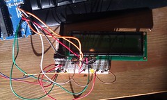
So, I wanted to create a shield for Arduino to make the LCD usage easier.
AVR-Ada includes library for HD44780-compatible LCD using 4 bits for data.
That means we need to use 4 pins for data, one pin for Enable signal, and one pin for Register select. Wiring on the shield therefore is something like this:

We also want a trimpot on the shield:
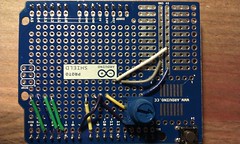
The middle pin of the trimpot is connected to the LCD pin 3 (Contrast adjust), other two pins are connected to GND and VCC.
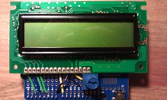
After placing the wires and the trimpot, we put the display there:
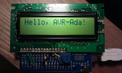
Finally, using code from my Bitbucket repository, we get some visible text:
Some notes:
- I used here Arduino UNO r3 with Arduino Protoshield r3.
- The Ada code requires AVR-Ada 1.2 (the latest development version from AVR-Ada git repository at the moment).
- If you fear that the LCD display might get damaged, you probably don't want to solder it directly to the proto shield but place female header between instead.
- My LCD display did not have working backlight, so I left those pins (15,16) disconnected.
Comments